Heat Sink Machining
CNC machined heat sinks and thermal components: pin fin heatsinks, cold plates and heat spreaders in aluminum 6063 and copper C110, interface flatness to ±0.001 in, Ra 16 µin finishes.
Last updated: 2026-10-29
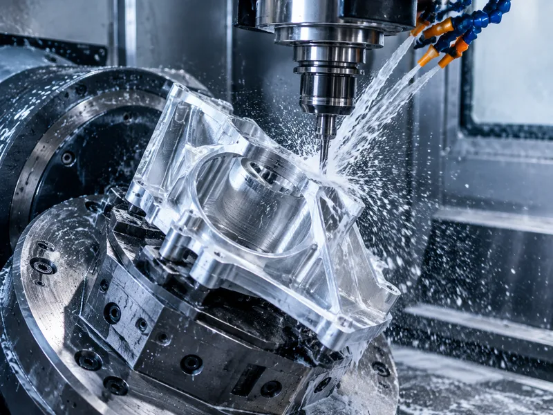
Machined heat sinks are the thermal hardware of electronics: pin fin heatsinks, liquid cold plates, heat spreaders, fan shrouds, vapor chamber bases and thermoelectric-mount plates, cut from thermally conductive metal with flat interface surfaces. Aluminum 6063 and copper C110 are the workhorse materials, chosen for thermal conductivity first and machinability second.
The specification that governs everything is interface flatness — flat thermal contact surfaces to ±0.001 in, so the thermal interface material actually contacts the source. Surface finish on contact faces (case-study parts ship at Ra 16 µin), fin geometry, and mounting features complete the drawing; lead times run market-typical at 5–10 business days for prototypes and 10–15 for production.
Specifications
| Specification | Heat Sink Machining |
|---|---|
| Tolerance | Down to ±0.001 in (flat thermal interface surfaces) |
| Axes | 5-axis machining produces thin, sleek heat sinks and complex parts in one go |
| Lead Time | 5–10 business days for prototypes, 10–15 for production (market-typical); documented case-study run shipped in 7 business days |
Materials
Surface Finishes
Heat sink machining produces the thermal hardware of electronics: pin fin heatsinks, liquid cold plates, heat spreaders, fan shrouds, vapor chamber bases and TEC mount plates in aluminum 6063 and copper C110. Interface flatness to ±0.001 in is the governing spec — flat thermal contact surfaces, with case-study contact faces at Ra 16 µin. Prototype runs quote market-typical at 5–10 business days, production 10–15.
Values above are the collected catalog specification envelope for this product family. Tolerances and lead times at the demanding end of a range are confirmed for the specific geometry, material and batch at quotation.
Applications & Selection Points
Pin fin heatsinks
Aluminum and copper pin fin heatsinks with dense fin arrays, flat TIM contact surfaces and mounting hole patterns. Fin geometry trades surface area against machinability — the array that machines reliably beats the array that only simulates well.
Liquid cold plates and heat spreaders
Cold plates and spreaders move heat where fins cannot: copper C110 spreader plates with precision-lapped thermal interface surfaces and component-matched footprints carry high-density sources. Flatness on the interface is the spec that decides thermal performance.
Enclosure-integrated thermal parts
Heatsink housings with integrated fin arrays, PCB mounting features and cosmetic anodized finishes combine the thermal and enclosure roles in one machined part — the documented case-study part ran 5-axis from 6063-T5 extrusion to a Ra 16 µin cosmetic finish.
TEC mounts and instrumentation plates
Thermoelectric cooler mounting plates need precise module pockets and wire-routing features; vapor chamber bases need wick-structure mounting and hermetic seal grooves. The machined route carries both the geometry and the flatness these assemblies demand.
Frequently Asked Questions
How flat can a machined thermal interface be?
Flat thermal interface surfaces machine to ±0.001 in, with case-study contact faces finishing at Ra 16 µin. Flatness beats alloy choice in many assemblies — a high-conductivity base that is not flat underperforms a flatter, lesser alloy.
Which material for my heat sink?
Aluminum 6063 for finned parts at cost, copper C110 where maximum conductivity governs — heat spreaders and cold plates — with 6061/7075 aluminum, titanium and brass carrying thermal-mount hardware. Composites appear where weight or isolation requirements justify them.
What does a heat sink quote need?
The model with fin geometry, the interface-flatness callout, alloy, finish (anodize, bead blast, brushed, polished) and quantity band. Prototype runs typically quote in the 5–10 business-day window, production 10–15 — say which stage you are buying.
Ordering & Documentation
Documents
Model plus drawing with the interface flatness and surface finish called out on contact faces, fin geometry dimensioned, alloy stated. Cosmetic faces should be flagged — they change the inspection and handling plan.
Quotation
Pricing follows fin complexity, alloy (copper machines slower than aluminum), finish scope and stage. Volume bands move the process choice — prototypes run one way, production batches another.
Sample & Supply
First articles check interface flatness, fin geometry and finish against the drawing; CMM dimensional reports on mounting features are the norm for cosmetic-grade parts. Production repeats from the frozen process and fixture.
Storage & Shipping
Copper interfaces oxidize — ship with protective packaging on contact faces. Anodized cosmetic surfaces need abrasion protection; fin arrays need crush protection in transit. Documentation ships with the parts when cosmetic-grade acceptance applies.