Robotics Machining
CNC machining for robotics: ±0.01–0.05 mm functional bands at precision interfaces, 6061-T6 and 7075-T6 frames, APQP/FAIR quality frameworks, quick-turn parts for robot programs.
Last updated: 2026-10-29
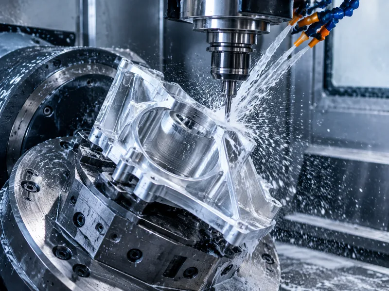
Robotics machining is precision work in service of motion: joints, frames, bearing seats, rail mounts and motion interfaces where a small deviation compounds into vibration, missed positions and calibration drift. The tolerance discipline follows function — critical interfaces run in the ±0.01–0.05 mm class, while non-critical geometry takes looser general tolerances — and the top end of 5-axis work reaches ±0.0001 in (±2.5 µm) where the application demands it.
The material canon is pragmatic: 6061-T6 aluminum as the default for frames and structures on the strength of cost and stability, 7075-T6 where stiffness-to-weight governs, and steel reserved for high-wear shafts and contact points. Quality frameworks carry over from regulated industry practice — APQP and FAIR inspection under an ISO 9001:2015 baseline — because a robot is a chain of parts whose tolerances stack into system accuracy.
Specifications
| Specification | Robotics Machining |
|---|---|
| Tolerance | ±0.01–0.05 mm functional band at precision interfaces; top end ±0.0001 in (±2.5 µm) reported on 5-axis work |
| Axes | 5-axis CNC machining serves complex custom robotics parts |
| Lead Time | As fast as 2 days (industry quick-turn benchmark); quick-turn supply quoted from 3 days |
Materials
Surface Finishes
Robotics machining covers the joints, frames and motion interfaces of robot systems, where tolerance discipline follows function: precision interfaces like bearing seats and rail mounts run in the ±0.01–0.05 mm class, 5-axis work reaches ±0.0001 in (±2.5 µm) at the top end, and non-functional geometry takes general tolerances. 6061-T6 aluminum is the structural default, 7075-T6 the stiffness-to-weight upgrade, steel the high-wear answer — with quick-turn parts as fast as 2 days keeping robot programs iterating.
Values above are the collected catalog specification envelope for this product family. Tolerances and lead times at the demanding end of a range are confirmed for the specific geometry, material and batch at quotation.
Applications & Selection Points
Joints, bearings and motion interfaces
Bearing seats and mounting faces are where motion originates — errors there compound into vibration and positional drift. Hold the ±0.01–0.05 mm class on those interfaces and relax everywhere else; precision spread across every surface buys cost, not accuracy.
Structural frames and skeletons
Chassis and structural parts prize predictable deflection over raw strength. 6061-T6 machines flat and stable for multi-face milling; 7075-T6 answers when the stiffness-to-weight ratio is the binding constraint. Design for the tolerance stack across the structure, not the single part.
Actuator, gear and wear components
Shafts, pins, rotary joints and gears put steel where wear actually happens. Turning carries the rotational components while milling secures flatness and hole alignment across mounting faces — the process split follows the geometry.
Prototype-to-production robot programs
Robot programs iterate: quick-turn parts as fast as 2 days keep design-validation loops moving, and the same platform carries the frozen design into batch production. Ask for tolerance inspection reports from real production parts — batch consistency, not a single fast delivery, is what keeps system calibration.
Frequently Asked Questions
What tolerances do robot parts actually need?
Functional features like bearing seats typically land in the ±0.01–0.05 mm band, with non-functional geometry looser. The failure mode is under-allocating precision at motion interfaces — or wasting it everywhere else. Tolerance stack-up across the assembly is the discipline that matters, since individually passing parts can still misalign the chain.
Which material for a robotic arm component?
6061-T6 aluminum for frames and non-critical structure, 7075-T6 when stiffness-to-weight governs, steel for high-wear contact. Match the alloy to the thermal and load environment — a robot that holds calibration is built from stable material choices made before the first cut.
What does a robotics machining quote need?
The 3D model and drawing with tolerances allocated by function, alloy and finish callouts, and the volume band. If APQP, FAIR or documented inspection is required, say so at quotation — it shapes the quality plan, and it is the framework robot programs increasingly audit for.
Ordering & Documentation
Documents
Model plus drawing with GD&T allocated by function — tight where motion originates, general elsewhere. Datum strategy matters: reference every operation to the same geometry logic or positional offsets accumulate setup by setup.
Quotation
Price inputs: stage (prototype or production), volume, material, tolerance allocation and documentation level. Tight functional tolerances slow cutting and add inspection loops — the quote reflects them, which is why allocation discipline is a cost tool.
Sample & Supply
First articles prove the interface features; request dimensional reports from production parts, not just the sample. Ongoing supply should be judged on batch consistency — one unstable batch costs more in system recalibration than days of lead time.
Storage & Shipping
Finished robot components ship with interface surfaces protected; anodized and bare aluminum faces need abrasion care in transit. Keep lot traceability intact so any assembly-level drift traces back to its manufacturing lot.