Wire EDM
Wire EDM cutting for hard conductive materials: tolerances from ±0.01 mm, parts up to 400 x 300 x 300 mm, up to five axes — carbides, graphite and hardened steels cut without cutting forces.
Last updated: 2026-10-26
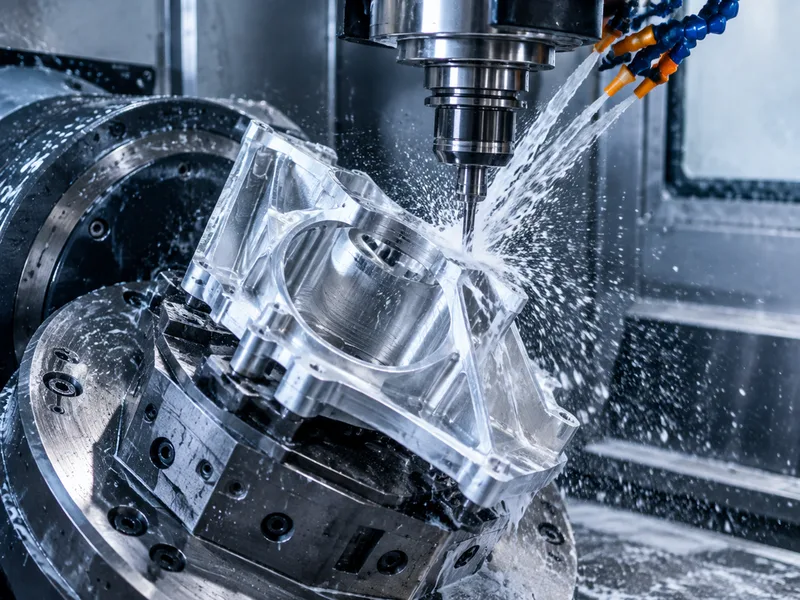
Wire electrical discharge machining cuts conductive material with a continuously fed brass wire carrying spark erosion along a programmed path. Because the wire never touches the workpiece, there are no cutting forces — which is why wire EDM is the process for hardened dies, carbides and delicate thin sections that would deflect or chip under a milling cutter.
The catalog envelope covers tolerances from ±0.01 mm and ±0.05 mm (down to a ten-thousandth of an inch on fine work), parts up to 400 x 300 x 300 mm, and machines of up to five axes for tapered and variable-profile cuts. Typical materials are the conductive and hard: carbides, graphite, hardened tool steels and electrically conductive exotic alloys. The material must conduct electricity — that is the one hard feasibility gate.
Specifications
| Specification | Wire EDM |
|---|---|
| Max Part Size | 400*300*300mm |
| Axes | up to five axes |
Materials
Surface Finishes
Wire electrical discharge machining service that uses a continuously fed wire electrode to cut conductive materials, capable of tight tolerances, fine surface finishes, and complex geometries. Suitable for hard conductive materials such as carbides and graphite.
Values above are the collected catalog specification envelope for this product family. Tolerances and lead times at the demanding end of a range are confirmed for the specific geometry, material and batch at quotation.
Applications & Selection Points
Hardened dies and punch tooling
Die openings, punch profiles and trim edges are cut after heat treatment, at full hardness, where milling would need annealing and re-hardening. The cut edge carries a recast layer and heat-affected zone characteristic of spark erosion — for long-life tooling, state whether that layer must be removed by a finishing skim pass or is acceptable at working conditions.
Carbide and graphite
Tungsten carbide wear parts and graphite electrode geometries are classic wire jobs: hard, abrasive, brittle under cutting forces, yet cleanly eroded by sparks. Fine surface finish on carbide comes from skim passes rather than from the first cut — spec the finish on the functional surfaces only.
Sharp internal corners and fine profiles
A milled internal corner inherits the tool radius; a wire-cut corner is limited only by the wire radius plus the spark gap — a fraction of a millimetre. Slots, holes and profiles with near-sharp corners in hard material are the geometry that justifies wire EDM over any alternative.
Tapered and variable-profile cuts
Multi-axis wire machines angle the wire through the cut, producing tapers, release angles on die components, and variable-profile extrusion dies. Conicity and taper tolerance interact with thickness — confirm the taper spec at quotation when it matters to part function.
Frequently Asked Questions
Wire EDM vs sinker EDM — which one for my part?
Wire EDM cuts through-profiles: the electrode is a stretched wire, so the result is a pierced or through-cut shape with near-sharp internal corners. Sinker (ram) EDM burns a shaped cavity into the part — blind cavities, mold details — where no through-path exists. If the feature goes through the part, wire is usually faster and cheaper; if it is a blind 3D cavity, sinker is the only EDM answer.
What tolerance and finish can wire EDM hold?
The catalog band runs from ±0.05 mm down to ±0.01 mm, with fine work quoted to a ten-thousandth of an inch. Surface finish improves with skim passes: the first cut is a roughing cut, and each skim removes recast and improves finish at added cycle time. Specify the finish on functional surfaces; letting the whole profile carry the finest spec multiplies pass count and price.
What does a wire EDM quote need?
A 2D profile (DXF/DWG) or 3D model, material and hardness state, thickness, tolerance and finish on functional edges, start-hole availability if the part is cut from a solid, and quantity. State whether the material is electrically conductive — it is the feasibility gate for the whole process.
Ordering & Documentation
Documents
Profile drawing (DXF preferred for through-geometry) with tolerance and finish callouts; for tapered cuts, the 3D model plus the taper spec. Hardness/heat-treat state of the incoming material should be stated — it changes the cut strategy.
Quotation
Pricing inputs: profile complexity and thickness (cut time scales with both), number of skim passes implied by the finish spec, material, quantity and destination. Where a finish spec is absent, quotes assume the standard two-cut sequence and say so.
Sample & Supply
Prototype die components and small batches are the normal order shape. For tooling, a sample component cut in the same material and hardness as the production run validates the edge condition before the full set is cut.
Storage & Shipping
Cut edges are clean but unforgiving of impact — carbide parts chip and fine profiles distort if packed loose. Parts ship edge-protected in fixed positions. Keep tooling components lightly oiled and separated in storage; re-polishing a damaged edge costs more than the protection would have.