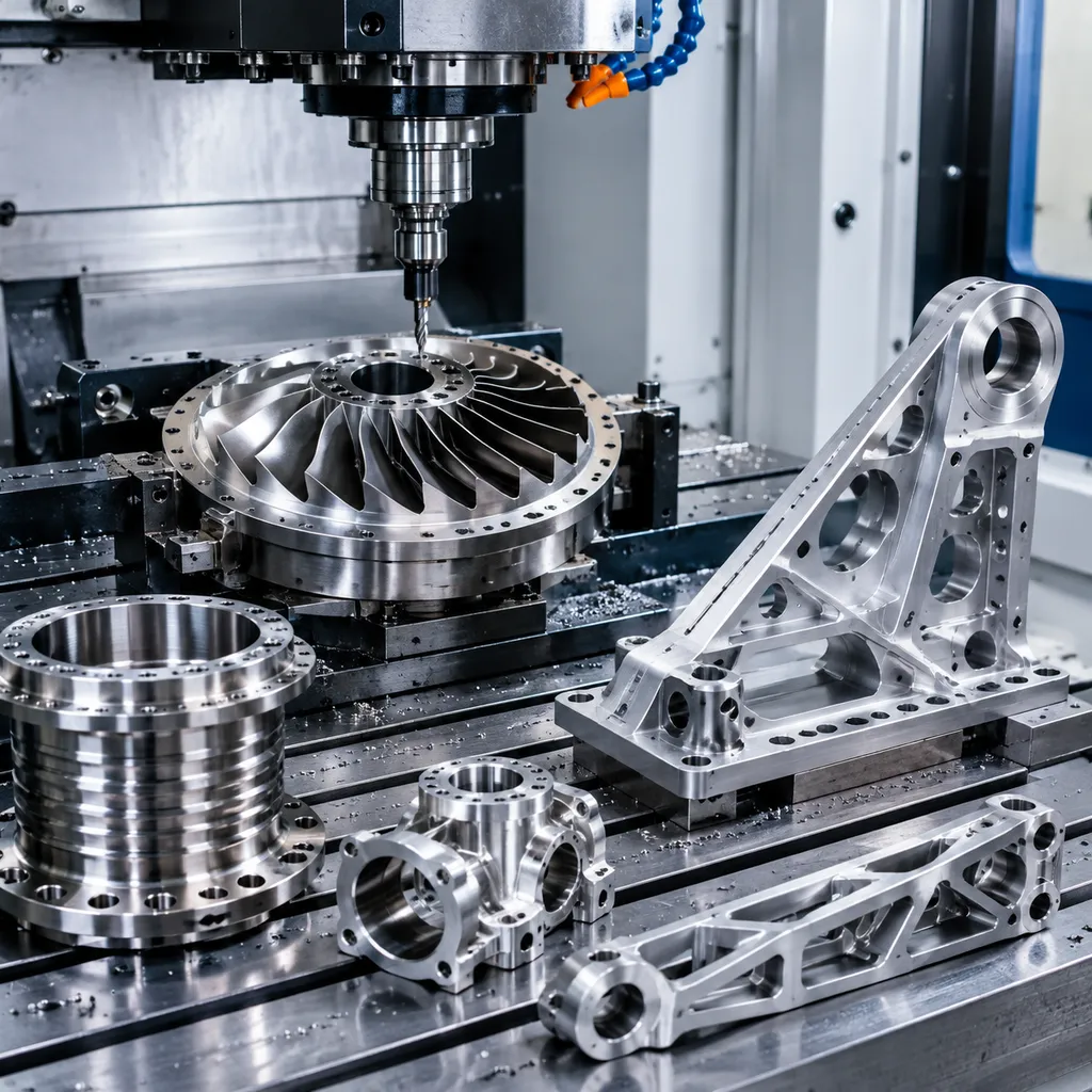
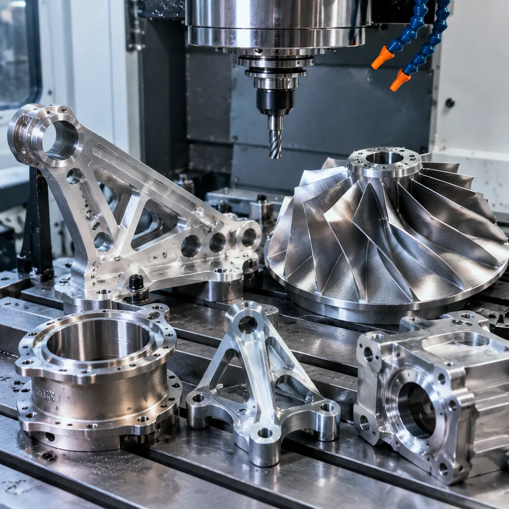
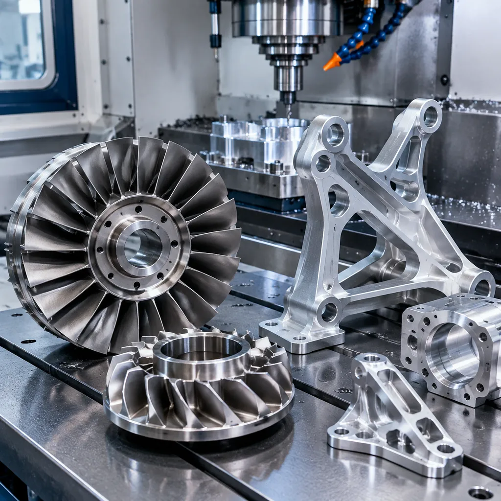
Typical Applications
- ✓Structural brackets, clips and fittings
- ✓Actuator and valve housings
- ✓Engine and APU components
- ✓Avionics enclosures and heat sinks
- ✓Ground-support and tooling fixtures
Process Capabilities
- ✓CNC Milling: 3-axis, 4-axis and 5-axis machining for complex geometries, thin walls and deep-pocket features
- ✓CNC Turning: Cylindrical components, threaded fittings and bushings with concentricity control
- ✓5-Axis Machining: Single-setup machining of compound-angle features and contoured surfaces
- ✓Wire EDM: Precision cuts in hardened materials and thin webs where conventional tooling cannot reach
- ✓Surface Grinding: Flatness and parallelism control for mounting surfaces and datum features
Materials for Aerospace CNC Machining
Titanium (Ti-6Al-4V), aluminum 6061/7075, stainless steel 303/304/316 and engineering plastics such as PEEK — selected for strength-to-weight, corrosion resistance and temperature performance.
Material Selection Guide
Titanium Ti-6Al-4V is the default choice for flight-critical structural parts because of its high strength-to-weight ratio and temperature stability. Aluminum 7075-T6 offers excellent machinability and fatigue strength for brackets and housings where weight matters but extreme heat does not. Stainless steel 316L provides corrosion resistance for hydraulic and fuel-system fittings. For non-structural enclosures and insulating components, PEEK and Ultem deliver reliable performance at a fraction of the weight of metal.
Tolerances & Precision
Standard tolerance ±0.1–0.2 mm (ISO 2768-m) covers most aerospace brackets and housings. Precision tolerances to ±0.05 mm are achievable on critical features — we review every drawing at quotation to confirm feasibility and cost. Tighter tolerances increase machining time and cost, so we recommend specifying them only on functionally critical dimensions and using GD&T to communicate the intent clearly.
How to Order
The aerospace procurement workflow starts with uploading your 3D model (STEP or IGS preferred) along with a 2D drawing that specifies tolerances, surface finish and material grade. We review the drawing for manufacturability, flag any concerns, and return a quotation typically within one business day. Once approved, production begins with first-article inspection on new part numbers, followed by in-process checks and a final dimensional report before shipment. For repeat orders, the approved first-article report serves as the quality baseline for all subsequent batches.
Quality & Documentation
In-house dimensional inspection on every batch; material certificates and first-article inspection reports available on request. Aerospace-specific certifications can be discussed case by case.
CNC Machined Parts by Material
Related Industries
Full Machining Capabilities
See the complete range of processes, finishes and tolerances on our CNC Machining Services page.
Frequently Asked Questions
Can you machine aerospace-grade materials like titanium?
Yes. Titanium Ti-6Al-4V, aluminum 7075 and stainless steels are part of our standard material range. Tight-tolerance calls are reviewed at quotation based on your drawing.
What documentation comes with aerospace parts?
Every batch ships with a dimensional inspection report. Material certificates and first-article inspection reports are available on request — tell us your requirements when requesting a quote.
What tolerance can you hold on titanium aerospace components?
Standard tolerance ±0.1 mm is typical for non-critical features. Precision tolerances to ±0.05 mm are achievable on critical dimensions depending on part geometry and feature access. Tighter tolerances are reviewed case by case at quotation.
Do you support both prototype and production aerospace orders?
Yes. There is no minimum order quantity for prototypes. Once a design is approved, the same workflow scales to repeatable low and mid-volume production batches with consistent inspection documentation.
Can you provide DFM feedback on aerospace drawings?
Yes. Every quote includes DFM feedback flagging features that may increase cost or risk — such as thin walls, deep pockets, tight internal radii or hard-to-reach tolerance callouts. This helps you optimize the design before committing to production.
Which file formats do you accept for aerospace part drawings?
STEP, STP, IGS, DWG and DXF files are accepted. 3D models (STEP/IGS) are preferred because they reduce interpretation errors, while 2D drawings with GD&T callouts provide the tolerance and finish specification.
How do you handle surface finish requirements for aerospace parts?
Anodizing (Type II and Type III hard coat), passivation, polishing and bead blasting are commonly requested for aerospace components. Surface finish is quoted based on your drawing callouts and material selection. Certificates for applied finishes can be provided on request.